GAMEROMS-SCAMMER
New Member
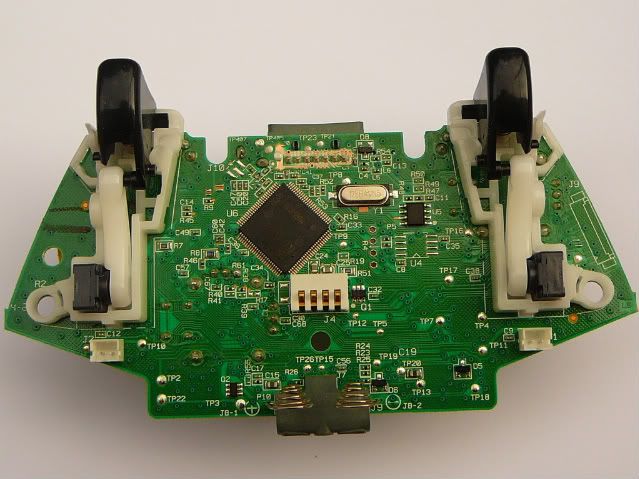
Well i've been trying to figure out a way to make a true sleeper and heres a few of the 1st pics. Not 100% its gonna work but im going to give it a hell of a shot.
I do not use the play and charge port on the controller since i have 6 rechargeable batteries and 3 chargers, so i've decided to try to disable the play and charge port and use it for programing.
CG BOTTOM
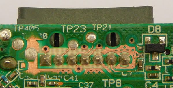
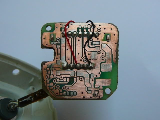
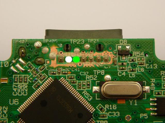
USED FIBERGLASS BRUSH TO CLEAN THE AREA AROUND THE PnC SOLDER CONNECTIONS SO IT WOULD BE EASIER TO FIND ALL THE TRACES
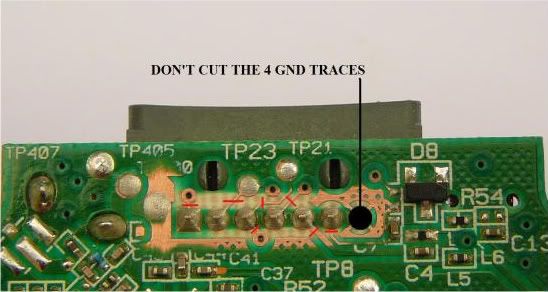
CUT THE TRACES AT THE RED LINES
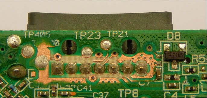
TRACES CUT AND TESTED WITH A CONTINUITY TESTER TO ENSURE THE TRACE WAS FULLY CUT
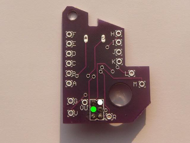
PnC USB Connector
NOTE: YOU DONT NEED TO CLEAN THE BACK OF THE PCB THE WAY I DID, I ONLY DID IT SINCE IT WAS THE 1ST ONE I WANTED TO LEARN THE TRACES. ALL YOU NEED TO DO IS REMOVE ALL SMT CHIPS, RESISTORS, ETC... THEN CUT THE RED WIRE SINCE WE PROGRAM WITH CONTROLLER POWER (SAME AS CUTTING THE PIN FROM PIN HEADER IF YOU GOT ONE WITH 4 PINS), AND IF YOU WANT THE LED TO BE SOLID RED WHEN IN PROGRAMING MODE AND FLASHING RED WHEN PROGRAMING JUST ADD THE RED AND BLACK WIRES AS SHOWN. THE ONLY 3 THINGS LEFT ON THE PNC PCB ARE THE WHITE CONNECTOR FOR USB WIRES, GRAY PnC CONNECTOR, and the LEDS. ONCE EVERYTHING IS REMOVED YOU DONT SOLDER ANYTHING UNLESS YOU WANT THE LED TO WORK THEN ADD THE 2 WIRES MENTIONED ABOVE. SINCE I EXPOSED ALL TRACES ON THE BACK OF THE PCB I COVERED IT WITH BLACK ELECTRICAL TAPE.
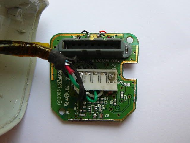
ADDING THE 2 WIRES NEEDED FOR PnC PROGRAMING
I do not use the play and charge port on the controller since i have 6 rechargeable batteries and 3 chargers, so i've decided to try to disable the play and charge port and use it for programing.
CG BOTTOM
USED FIBERGLASS BRUSH TO CLEAN THE AREA AROUND THE PnC SOLDER CONNECTIONS SO IT WOULD BE EASIER TO FIND ALL THE TRACES
CUT THE TRACES AT THE RED LINES
TRACES CUT AND TESTED WITH A CONTINUITY TESTER TO ENSURE THE TRACE WAS FULLY CUT
PnC USB Connector
NOTE: YOU DONT NEED TO CLEAN THE BACK OF THE PCB THE WAY I DID, I ONLY DID IT SINCE IT WAS THE 1ST ONE I WANTED TO LEARN THE TRACES. ALL YOU NEED TO DO IS REMOVE ALL SMT CHIPS, RESISTORS, ETC... THEN CUT THE RED WIRE SINCE WE PROGRAM WITH CONTROLLER POWER (SAME AS CUTTING THE PIN FROM PIN HEADER IF YOU GOT ONE WITH 4 PINS), AND IF YOU WANT THE LED TO BE SOLID RED WHEN IN PROGRAMING MODE AND FLASHING RED WHEN PROGRAMING JUST ADD THE RED AND BLACK WIRES AS SHOWN. THE ONLY 3 THINGS LEFT ON THE PNC PCB ARE THE WHITE CONNECTOR FOR USB WIRES, GRAY PnC CONNECTOR, and the LEDS. ONCE EVERYTHING IS REMOVED YOU DONT SOLDER ANYTHING UNLESS YOU WANT THE LED TO WORK THEN ADD THE 2 WIRES MENTIONED ABOVE. SINCE I EXPOSED ALL TRACES ON THE BACK OF THE PCB I COVERED IT WITH BLACK ELECTRICAL TAPE.
ADDING THE 2 WIRES NEEDED FOR PnC PROGRAMING
