PS4 ragnarok No signs of life

mod-fx2b

New Member
Hey guys, pulling my hair out with this one.20160109_184540.jpg 20160109_184540.jpg 20160122_214853.jpg I have triple checked everything with this install and I can't find anything wrong. For starters I have extensive experience with installs for consoles, controllers, mobile phones, and laptops. Now with that aside I'm also experienced enough to know i'm not above mistakes. Unfortunately with this one i can not find any mistakes, no shorts, no bad connections, no crimped wire. Just no signs of life. I originally had all the tacs wired up and have since removed everything but LS RS V and G. I do have 3.2v on the chip measured from G and V on the chip. No LED from chip ever. So this has been a process of double check, plug in ribbon cable from back of controller, plug in usb, no led, open back up check again, plug in ribbon cable,plug in USB, No LED, wash rinse repeat. I'm attaching pics but understand some were prior to me removing all the tacs for elimination. Also in reviewing my pics I've noticed what appears to be a missing solder ball from the PIC and was wondering if this is intentional, could be a manufacturing defect, or might cause it to be DOA?
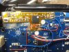
20160122_215350EDIT.jpg
 

Attachments

  • 20160122_215014.jpg
    20160122_215014.jpg
    3.4 MB · Views: 2

odingalt

Well-Known Member
Staff member
The Sony PS4 controller has a power saving feature. If the controller isn't talking to a console or a PC (via wired USB), it will power down the trigger circuits. The modchip doesn't work at all (appears dead) when the trigger circuit is powered down. To get the modchip LED driver to ligh tup, the controller must be sync'd to a console or a PC (via wired USB). I have to mention this because I don't think we have it in our documentation, but this has tripped up lots of experienced installers (about 30% of our wholesale clientele on their first try actually). Did you have this thing synced to a nearby console, or plugged into a PC by wired USB?
 

mod-fx2b

New Member
Yeah, I originally was in pc with usb like I usually do but to rule it out went to ps4 with usb with same effect.
 

odingalt

Well-Known Member
Staff member
On the two pads at "TAC4". The "left" pad has a blue wire. That blue wire doesn't make sense to me. It shouldn't cause any problems, but as an FYI on this particular modchip I think it makes the ground connection from the flex connector. Multiple grounds shouldn't be a problem.
 

odingalt

Well-Known Member
Staff member
If the LED driver board or ribbon cable is failed the mod will look dead (no lights). Not sure exactly how to tell the difference between problem with modchip and wiring vs. problem with LED driver board and ribbon cable.

Is the ribbon cable you have there a "straight/same side" cable (meaning if you laid it flat on a table the blue side is up on both sides, or the connector side is up on both sides). Is there a way to do an ohm check from the header on the modchip to the header on the LED board to confirm those four connection inside the ribbon cable are making their way through successfully?

I don't see anything in the photographs. I'm trying to rack my brain for other troubleshooting tips but we don't run into many issues with these particular modchips.
 

mod-fx2b

New Member
Checked, and triple checked. Yes the ribbon cable is one that you guys were gracious enough to send me cuz I needed a longer one. Same side. I did a continuity check between led board header and header on mod chip. All good. The blue wire going to left pad of tac 4 was where I connected ground at first. I traced the G pad to find all the ground points for tacs and used the most convenient source for wire management. When I removed all tacs I moved ground directly to the G pad just to be sure. Thank you for the suggestions. I keep hoping there's just something I've missed. Did you see what I was talking about in the last pic? It really looks like that pin isn't soldered at all but I know sometimes there are intentionally dead or cut pins on some chips.
 

odingalt

Well-Known Member
Staff member
Yes I saw that, it's normal on these chips. There is some solder starvation on that pin so to speak, it is because there is no soldermask (dam) from that pad to the center ground pad, so the solder deposited on that pin is free to make it's way underneath the PIC chip to the main ground pad during reflow.
 

Freyja

Member
Staff member
Did you already go through the unlock phase, or has this controller not been able to power on, regardless of being plugged in or not, since the chip was installed?
Edit:
Personally I would use more solder on the chip. I always go for little shiny mounds on the pads after the wire has been soldered down without any of the wire or wires shape showing. The amount there is now is probably OK, but I'm in the practice of making sure all connections are as secure as possible.
 

mod-fx2b

New Member
The first couple of times I plugged it in and didn't get any led light from the chip I touched nothing and unplugged. When I do this the controller powers on and syncs (solid blue led from controller) no led from mod. After the third time, worrying that the mod chip was on, but just not showing led, I tapped triangle over 50 times then unplugged. Rechecked connections etc and retried later. I will reflow the pads on the chip and see if there are any changes. Thanks for taking the time to follow up here.
 

mod-fx2b

New Member
I've seen on the forums for xb1 version recommendations to do an led / button test. Is there a sequence I can press to do an led / button test on ps4 ragnarok?
 

mod-fx2b

New Member
Ok, finally signs of life. I did the reset to default procedure and led's lit, it reset, and I can turn mods on and off. I found the led / button test instructions in the ragnarok rev-d manual. I did that and all led's and tac's are working fine. I have not been able to remap the tac's . There is no procedure in the manual for how to program the remap. The remap chip manual has you using the options button but I'm pretty sure in that install the options button is tied to s2. So the question, is s2 used to get into programming mode to remap the tac's? I've tried holding the mod switch for 3sec to get into programming mode but that didn't work. In this install mod switch is tied to tac1. So, am I doing it wrong or do I need to wire s2 to activate programming mode to remap?
 

WHITE 4ND N3RDY

ModdingBros Representative
To program the remap tacs all u do is use your main tac switch (the one u use to activate the mods) then tap the PS home button. From there the quad led will flash white. Now just tap the tac u want to remap and the quad led will flash once in white. This means that tac is ready to remap. Now just hit the button u want to map to the tac and the quad led will flash white twice, confirming the remap. Continue this on the rest of your tacs for your desired remaps. When your done just tap your main tac "mod tac" and the quad leds will flash white "I believe " 4 times real fast confirming u exited the programming feature. If I want to disable a remap just do the same steps listed above and use the PS home button as if u were going to map it to the tac. It will disable the remap from the tac making it disabled till u decided to remap the tac again by accessing programming mode.

Let me know if this works for u!
 

odingalt

Well-Known Member
Staff member
Freya to the rescue, nice tips!

There are two different modchips:

Pro Remap modchip
Ragnarok modchip

For the Ragnarok chip, the instruction you want are on page 20 "Re-mappable Buttons (white)". (It's the very last page of the operation instructions, I'm looking at the 9-26-2015 edition that is currently on the product page). Here's the excerpt:


What are Re-mappable Buttons?
Extra buttons can be installed on the mod, and these extra buttons can be re-mapped to perform the action of any stock button. For example, the re-mappable button can be set up to control the right stick, so that any time the user presses the re-mappable button, the mod presses the stick for them. Re-mappable buttons are normally used so that the player doesn’t have to move their thumbs away from the thumbsticks during gameplay.

How do Programmable Re-mappable buttons work?
If you have programmable re-mappable buttons, you can change the assignment of your re-mappable buttons through the programming menu. Hold mod switch + tap PSHome button to enter the mod programming menu. All four LED’s will turn white, and then the mod waits for you to enter a selection. Press any re-mappable button to program that button, and the four LED’s will blink once slowly to let you know it’s ready for your selection. Then press any stock button. The four LED’s will blink twice to confirm that it accepted your selection.

To configure more than one re-mappable button, continue pressing the re-mappable button you want to configure (mod will blink slowly once) and then press the stock button you want to assign to that re-mappable button (mod will blink twice).

When you’re all done configuring your re-mappable buttons, and are ready to save your changes, hit the mod switch. All four LED’s will blink quickly three times to confirm that your new settings were saved, then the mod will then exit the programming menu.
 

mod-fx2b

New Member
Omg, I feel like the biggest noob since the second guy who discovered fire. I swear I looked through every pdf and the forums and couldn't find that. I don't know how I missed it. One mistake, after looking through a couple pdf revisions I did a word find in them for remap and came up with nothing cuz it's re-mappable. :/ So beyond the embarrassment I want to thank you guys for all your help. The support here has been outstanding and truly a model for any business that has customers. I would like to write a review of the site and support in the most beneficial place to you guys. If you could tell me where it will have the most effect for you I will gladly post it. I'll even use spell check and make it look Purdy. :)
 

odingalt

Well-Known Member
Staff member
You're not the first one to miss it on the last page. I've actually missed it myself when looking for the instructions. It's like the page-down button gets jammed when viewing the .PDF or something. I don't know what the deal is but I have to say that it's out of place to have the remappable button instructions on the very last page of the Ragnarok operation manual, for some reason.

We are just happy to have DIY guyshanging out in our forums. The biggest favor you can do for us is just to stop by these forums from time to time and share any info on any other DIY projects you brew up, whether they are even related to Viking or not. It's nice to have other hobbyists around to chat with.
 

WHITE 4ND N3RDY

ModdingBros Representative
Man I need to get around to installing my other ps4 rag mod lol. Been too long since I put down some sweet solder. I still have a xb1 pro remapper kit as well. Loos like it's time to dig my station out of my garage and get to modding. I would like to get my hand on an elite controller as well and see if I could install the rev d rag chip. I figure everything will fit in the underside of the boomerang pcb. Courious to see if the paddles are compatible with any of the rag features or if the will even work to activate mods! Would be nice to be the first one to do it. Though I do take pride in being the first person I heard of to install a Nintendo 3d's slider in place of the xb1 d pad!!!
 

modded matt

Active Member
you better move fast. My Elite is being delivered today finally, but Ii guess its a mute point as the Rag has been discontinued.
 
Top