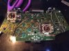
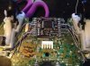
Ok, here goes. I recently bought a ragnarok chip DIY kit. Been screwing around with 555 timers and PICs for a minute now, but I wanted something more, so I thought I'd give this a shot. Everything seems to have gone great.....except for the tactile switch.
The switch itself seems to work fine. Clicks. Reads fine on my meter. Problem is when I hold the switch and attempt to turn on or off any feature the player 3 LED blinks twice, then once. Repeats that pattern for as long as I hold the switch.
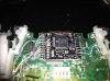
I've soldered the USB port on and the computer reads the mod chip fine. Both the firmware updater and the modification app see the controller and can update it, as well as reset it etc. And when connected the player 4 LED lights up. Both the player 3 and 4 LED blink rapidly when attached to the computer. I'm guessing this is an "I'm connected" state, display.
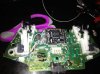
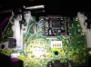
I will be removing and resoldering all the wires when I get home (typing this on my phone). I will also post pics of the original before reworking.
It seems to me that there is a short on one of the buttons. The only button I did different was the B pad, I scuffed the bottom of the pad instead of the top.
I am using 30awg insulated wrapping wire. Wonder if that's the problem? I'm thinking I'll change it all for some wire from an old IDE cable I've got here. All the electronics shops here only have 24awg.
Other thoughts, ideas, "Oh, I've seen this before....", anything is welcome.
Pics coming soon.
Otherwise, very pleased with the product itself. Fast shipping. Cool features. Easy enough to install....ahem(degree in electromechanical engineering helped a little).
Most likely user error.
EDIT: issue solved, user error. Solved by soldering to the CORRECT pads!!! Duh!!
Lesson learned no late night solder projects with out scads of coffee.
The switch itself seems to work fine. Clicks. Reads fine on my meter. Problem is when I hold the switch and attempt to turn on or off any feature the player 3 LED blinks twice, then once. Repeats that pattern for as long as I hold the switch.
I've soldered the USB port on and the computer reads the mod chip fine. Both the firmware updater and the modification app see the controller and can update it, as well as reset it etc. And when connected the player 4 LED lights up. Both the player 3 and 4 LED blink rapidly when attached to the computer. I'm guessing this is an "I'm connected" state, display.
I will be removing and resoldering all the wires when I get home (typing this on my phone). I will also post pics of the original before reworking.
It seems to me that there is a short on one of the buttons. The only button I did different was the B pad, I scuffed the bottom of the pad instead of the top.
I am using 30awg insulated wrapping wire. Wonder if that's the problem? I'm thinking I'll change it all for some wire from an old IDE cable I've got here. All the electronics shops here only have 24awg.
Other thoughts, ideas, "Oh, I've seen this before....", anything is welcome.
Pics coming soon.
Otherwise, very pleased with the product itself. Fast shipping. Cool features. Easy enough to install....ahem(degree in electromechanical engineering helped a little).
Most likely user error.
EDIT: issue solved, user error. Solved by soldering to the CORRECT pads!!! Duh!!
Lesson learned no late night solder projects with out scads of coffee.
Attachments
Last edited: